
When I was searching the web and looking for different ways to create fog effects, I noticed that most tutorials used Shuriken and smoke texture animation sheets. In addition, the fog effects were not low-lying but rather tall, and unfortunately, scaling it down and making it float near the floor did not make it look that pretty, so I made my own, which is why I am sharing with you this tutorial!
This low-lying fog effect is created with Unity’s ShaderGraph and can be tweaked to look realistic or stylized, and looks great on water surfaces or simple terrain. The core idea of this fog effect is that we are using a noise texture to offset the vertices of the plane object and adding more nodes to make it look pretty.
By learning how to create this low-lying fog effect you will also know how to:
1. Render a texture from shader;
2. Offset vertices of your model;
3. Add depth fade to your effects or models;
4. Use ramp color textures.
If these concepts sound difficult to you do not worry! Everything will be explained and broken down into very little steps so you can learn and understand as much as possible!
This tutorial is broken into 2 parts:
1. Getting started
2. Shader creation
2.1 Displaying the main texture;
2.2 Offsetting vertices;
2.3 Adding color (ramp textures);
2.4 Adding depth fade;
2.5 Adding the mask texture.
Requirements:
- Unity 2020.1+, HDRP;
- Have a basic understanding of Unity’s UI.
1. Getting started
If you would like to follow along, create a new High Definition Rendering Pipeline (HDRP) project and import noise texture files and the plane mesh into the project. We are not using Standard Rendering Pipeline (SRP) as it does not have the ShaderGraph feature. This tutorial may work on URP, I don’t see why it shouldn’t, however, due to time restrictions, I cannot fully test it, so if you decide to recreate it on URP and run into some issues let me know, and we can troubleshoot it together.
If you would like to take the route from the other side and explore yourself, you can also download the complete project with all the noise textures, plane model, and the finished shader.
GDrive for project file downloads
The provided files are under CC0 license (you can enhance and reuse the works for any purposes without restriction under copyright or database law).
I also encourage you to try to experiment with your own textures. If you are thinking about making a bigger plane object, please keep in mind that the more subdivisions it has, the more smooth the movement of the fog will look.
We will be working on the ‘SampleScene.unity‘ scene as the lighting is already set up.
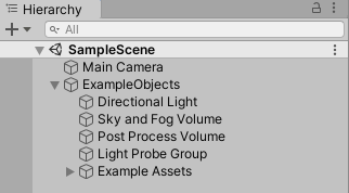
- Open SampleScene.unity and in the hierarchy create a new empty object, then group all of the objects in the scene so that it would look like in the hierarchy image below. We will then collapse the newly created Game Object so that we could have a cleaner hierarchy. I always like to keep the camera outside so that I could easily change the view.
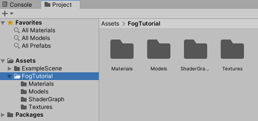
- In the Project window organize your imported files as below or how it suits your needs. I also created a folder for the example scene files and dragged everything into one folder.
- Locate the noise textures and click on them to access the Import Settings. In the settings change ‘Alpha Source’ to ‘From Gray Scale’ and click ‘Apply’. This will allow complete transparency on the black areas of noise texture as this setting generates alpha from the mean (average) of the input Texture RGB values.

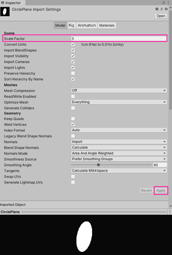
- Locate ‘CirclePlane.fbx’ in your imported files, open it, and set the Scale factor to 5, apply the changes. Drag the object into the scene.
This is how the project should look like after all the setting up:
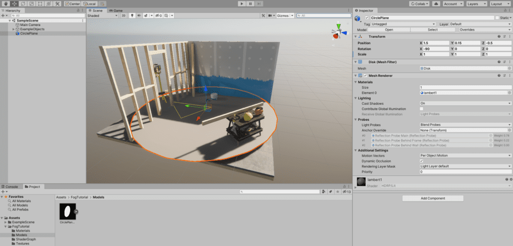
And we are done with setting up! 🥳
2. Shader Creation
This is the full shader that we will be creating (you can open it in a new tab to view it clearly). This might look a bit overwhelming at first but everything is explained thoroughly, so do not get discouraged!
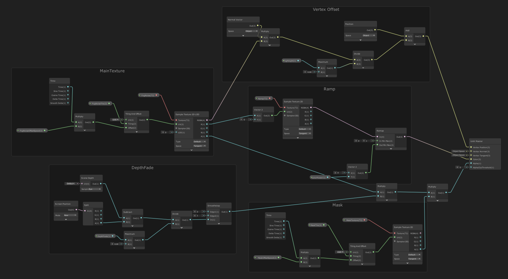
Let’s create!
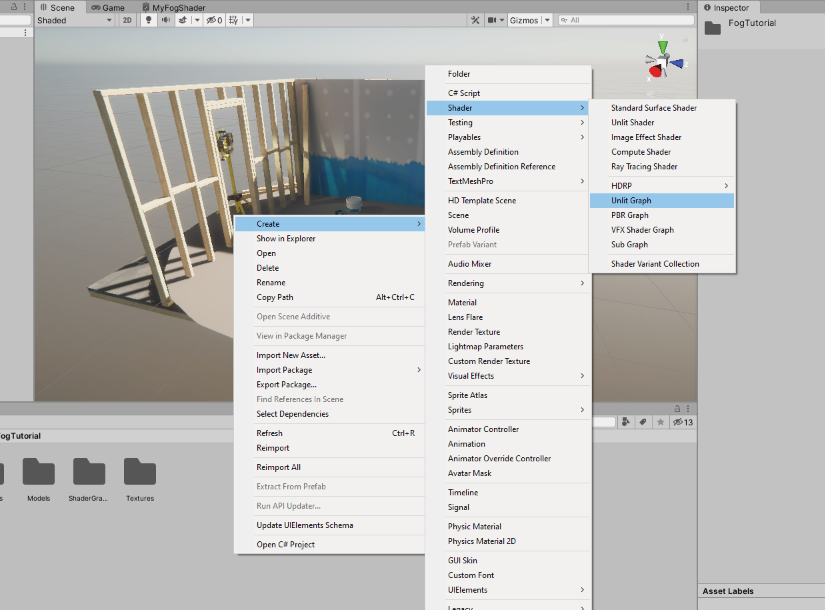
- Create a new ShaderGraph by right-clicking on the project window and selecting Create>Shader>UnlitGraph. Name the Shader.
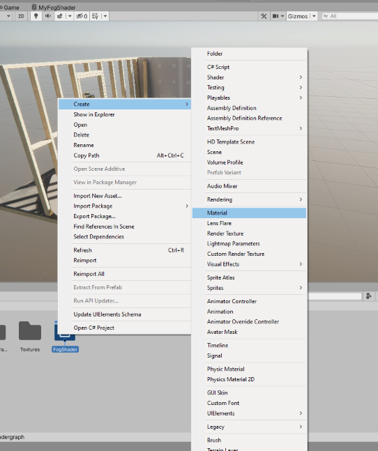
- Once the ShaderGraph is created, right-click on the ShaderGraph, Create>Material. This will automatically create a material that will have the newly created shader applied. Name the material.
- Drag the newly created material to the scene on the ‘CirclePlane’ object.
- Organize the project – put the newly created objects into appropriate project folders.
- Double click on the created ShaderGraph. This will open the ShaderGraph window where we will add nodes.
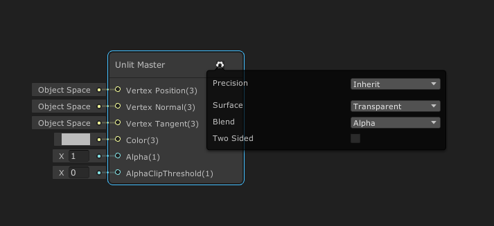
- In the ShaderGraph window, we will find our ‘Unlit Master’ node. Click on the cog-wheel icon to change the surface type into Transparent, since the fog is transparent.
2.1 Displaying the main texture
The first thing that we will do is to make the shader display, tile, and offset our noise texture. To do this we will begin to add nodes to our ShaderGraph. First of all, we will add new properties to the ‘Blackboard’. These properties will be exposed and we will tweak them in Editor.
- In the ShaderGraph window, open the ‘Blackboard’.
- In the ‘Blackboard’, click on the plus icon and choose Texture2D. Name the new property to ‘FogNoise’ (or anything that you would like). This is the property where we will assign the noise texture in the Editor.
- In the ‘Blackboard’, click on the plus icon and choose Vector2. Name the new property to ‘FogNoiseTile’. Set the x and y values to 1.
- Repeat the last step but rename the property to ‘FogNoiseOffsetSpeed’. Leave x and y values as 0.
So far the ‘Blackboard’ should look like this:

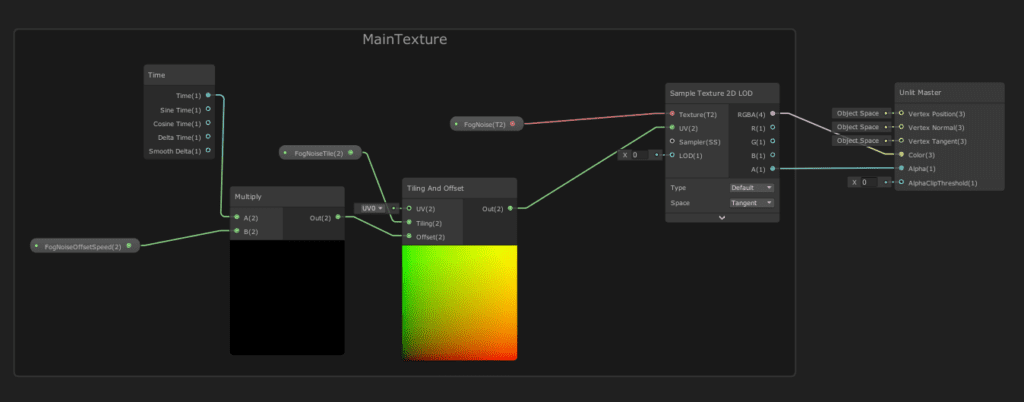
- Start to add nodes and match the image below. Please note that I dragged the properties from the ‘Blackboard’.
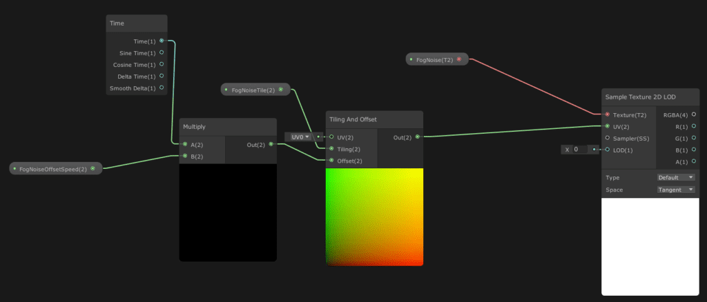
‘Sample Texture 2D LOD’ is the main texture node that will gather all the important information for the texture to be displayed and will turn into RGBA channels. We input our ‘FogNoise’ property node into Texture so that the particular texture would be displayed. We then add the ‘Tilling And Offset’ node so that we could be able to tile our noise texture and offset (animate) the models’ UV’s so that it would appear that the texture is scrolling. We will be able to control the scrolling speed by entering our custom value which will then be multiplied with time. We are using ‘Sample Texture 2D LOD’ instead of ‘Sample Texture 2D’ as we will use the texture in the vertex shader stage to offset the model’s vertices. If you won’t be using the texture to offset vertices I recommend sticking to ‘Sample Texture 2D’.
If we continue to output RGBA(4) and A(1) from ‘Sample Texture 2D LOD’ to ‘Unlit Master’ node Color and Alpha slots we will be able to see the texture in the Editor.
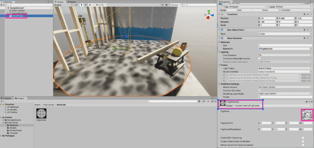
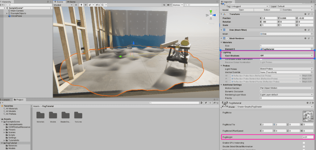
Of course, firstly, we will need to set which texture we would like to be displayed in the Editor. This is done so by selecting the Material which has this specific shader applied and adding the texture into the slot.
We can also tweak the tilling and scrolling, to check if it works! Woaaah 😮
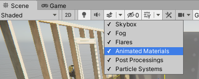
If you don’t see the material scrolling make sure that have turned on ‘Animated Materials’ under the Scene tab.
This concludes the first part of the ‘Shader Creation’ chapter. Now you should be able to display, offset, and tile the texture! Before moving further with the tutorial remove RGBA connection from the ‘Unlit Master’ node 😉

2.2 Offsetting vertices
In this part, we will learn how to offset the vertices of the model according to our noise texture.
- Add a new Vector1 property to the ‘Blackboard’ and call it ‘FogHeight’.
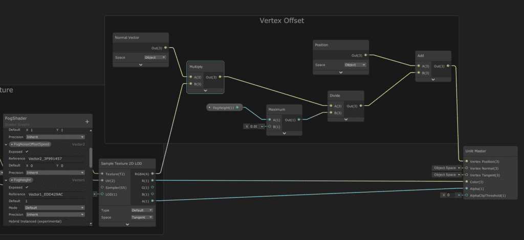
- Start to add nodes and match the image below. ‘Maximum’ node x value is set to 0.0001. Please note that ‘Normal Vector’ & ‘Position’ nodes have their Space set to ‘Object’. Connect ‘Multiply’ node with ‘Sample Texture2D LOD’ node from the first part of the tutorial and ‘Add’ node to the ‘Unlit Master’ node ‘Vertex Position’ section.
Add a new Vector1 property to the ‘Blackboard’ and call it ‘FogHeight’.
Start to add nodes and match the image below. ‘Maximum’ node x value is set to 0.0001. Please note that ‘Normal Vector’ & ‘Position’ nodes have their Space set to ‘Object’. Connect the ‘Multiply’ node with the ‘Sample Texture2D LOD’ node from the first part of the tutorial and the ‘Add’ node to the ‘Unlit Master’ node ‘Vertex Position’ section.
Essentially what’s happening here is that we are multiplying RGBA values with the normal vectors of the object and then adding new positions for them, controlling the height. The white parts of the textures have a value of 1,1,1 while the blackest parts have 0,0,0 so when we multiply these values with the ‘Normal Vector’ node, the white parts will have a bigger value than black, thus will appear higher, so when we add the same new position value to the white parts it will still be higher. The ‘Divide’ node is there so that we could have smaller values and could control the height of the fog. We run our float value through the ‘Maximum’ node so that if we ever choose zero value it will be converted to 0.0001 so that we wouldn’t divide it by zero,
Once we tweak the offset speed values of the noise texture we can see that the fog is offsetting the vertices and looks like it is waving 🌫️ If it’s starting to look more and more like a fog you are on the right path!
With vertex offsetting, different noise textures yield different results, take a look at some examples below, try to experiment, and explore yourself.
This concludes the second part of the Shader creation chapter and you should be able to offset the vertices of the object according to the texture’s color values 🤯
2.3 Adding color (ramp textures)
In this part, we will be adding color to our fog by using a ramp texture. This technique is used so we could have different colors targeted at the specific parts of the texture. The ramp texture is essentially a colorful gradient, which gets assigned to a gradient ranging from black to white. Take a look at this example:
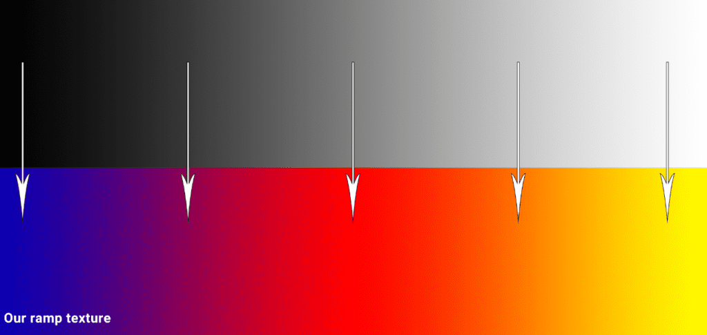
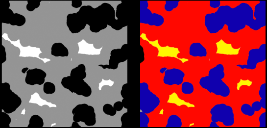
In this example, our ramp texture is ranging from blue to pink, to red, to yellow. Since blue falls right beneath the black, our black parts of the texture will be assigned the color blue, the gray parts will be red and the white parts will be yellow. If we had any other grayish hues in our noise texture they would be assigned the color which follows “beneath it”. So with that in mind, we can assign different colors at once to the same texture. Also, a quick note, since we only read the information horizontally and the colors stay the same vertically, we only really need texture’s width, so to save up resources the ramp textures are usually exported 265×1.
Of course, you might ask, why not just color the noise texture in the first place?
Well, that is super time-consuming and you won’t be able to make as many different iterations as you could. Once you have a folder with lots of different ramp textures just imagine how fast it will be to change the noise texture’s colors!
There are multiple ways how to create ramp textures but I won’t be sharing the techniques now, since this tutorial is very long already, however, I will share these techniques in my future posts, so stay tuned!
Now let’s continue with the fog shader…
- Add a new Texture2D property to the ‘Blackboard’ and call it ‘Ramp’.
- Add a new Vector1 property to the ‘Blackboard’ and call it ‘ColorPower’. With this, we will control how strong/saturated the colors of the ramp will be.
- Add nodes like in the picture below to the shader, and connect them with ‘Sample Texture 2D LOD’ from the first part of the tutorial and also with the ‘Unlit Master’ node to the Color section.
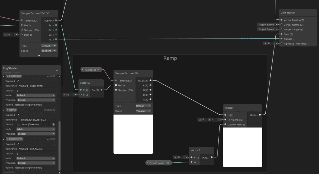
Here we are getting the R channel from the noise texture and running it through Vector 2, x input. Since we are only reading the texture from left to right along the x-axis or this particular situation along U, we set the Y (or V) to 0. We then input this to the ‘Sample Texture 2D’ node where we also input the ramp Texture2D property. These nodes are enough to assign the ramp texture’s color to the noise texture and if we would go ahead and take RGBA values and input them to the ‘Unlit Master’ node’s Color section right now, you would see the colors assigned.
Let’s do the extra mile and add a ‘Remap’ node. The ‘Remap’ node allows us to basically remap values from one range to another. We are defining that our current values are ranging from 0 to 1 and we will be remapping them from 0 to how much we want with the ‘ColorPower’ property, this will allow us to control how strong the colors from ramp texture are. We then output the result to the Color section of the ‘Unlit Master’ node.
- Go back to the Editor and assign the ramp texture to the right field:

The whitest parts of the texture are now light blue and the darker parts are dark blue! See what also happens when we play with the ‘ColorPower’ property below… The bigger the number the lighter it becomes, the lower – the darker.
This concludes the third part! By now you should be able to know how to use ramp textures for coloring. I really hope that you will be able to apply this knowledge to your projects.
2.3 Adding depth fade
In this third part, we will be adding depth fade to our fog shader so that the fog would surround the objects in a nice way without leaving harsh edges. I actually like to add depth fade nearly to all of my effects as it helps to blend the effect with the environment.
- Add a new Vector1 property to the ‘Blackboard’ and call it ‘DepthFade’.
- Add nodes like in the picture below to the shader. We will also multiply depth fade nodes with the ‘Sample Texture 2D LOD’ node’s alpha channel so that we would still receive alpha from the main texture and new alpha from depth fade.
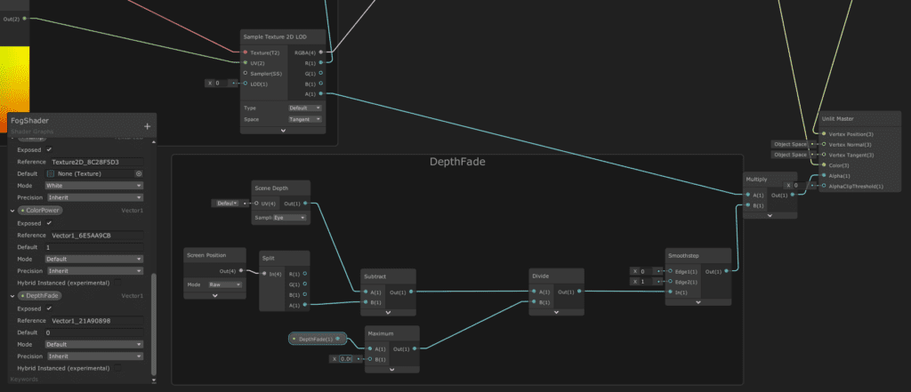
We take the ‘Screen Position’ node and set it to ‘Raw’. This node returns our screen position and because we set it to ‘Raw’, it does not divide the screen position by the clip space position W component (useful for projection). We then split this node so we could only get the Z information. We subtract the Z information from screen depth and we divide the result by a float value which we will control. The float value also goes through the ‘Maximum’ node which means that the closer our float value to 0.0001 is, the harder the edge will be, the bigger the float value is the softer it will be (note: ‘Maximum’ node’s B value is set to 0.0001 because division by 0 is not applicable. The ‘Maximum’ will convert the 0 value to 0.0001) We then put it through the ‘Smoothstep’ node which just smoothes out the overall fade (if you are interested more about how the smoothstep function works you can watch a video about it here). We then multiply it with noise texture and put it into Alpha.
Once we change the ‘DepthFade’ property in the Editor it should look something like the gif below. The bigger the number, the softer the edges are where the objects are intersecting. Also, in this gif I changed the ramp texture from blue colors to grayish.
As I mentioned before, depth fade is quite useful for any effect that you are making because it will make the effect look more professional and it will blend with the environment seamlessly. If you are new to VFX making, I would say this is the most useful thing from this tutorial that you can get, so save it and remember it in the future!
2.4 Adding mask texture
In the last part, we will be actually doing the same thing as in the first part with some minor changes. We will now add the mask texture, which will also tile and offset just as our fog noise texture. This step will add a more polished look to our fog.
- Add a new Texture2D property to the ‘Blackboard’ and call it ‘MaskTexture’.
- Add a new Vector2 property to the ‘Blackboard’ and call it ‘MaskTile’.
- Add a new Vector2 property to the ‘Blackboard’ and call it ‘MaskOffsetSpeed’.
- Add nodes like in the picture below to the shader. We will also multiply mask nodes with the ‘Multiply’ node that we added in the previous part and then put it to the Alpha channel of the ‘Unlit Master’ node.
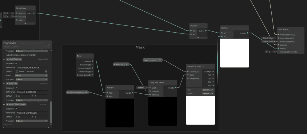
Basically everything the same just as we did in the first part, but we are only getting the Alpha of the mask texture. We are using this mask texture to tone down the fog and also add some new cut-outs. When we offset both textures and layer them we get more depth in the fog.
Aaand…
That’s it! We are done. At least I am done. You should go ahead and tweak the properties and experiment with some textures! In the project which I provided, there are some textures that I did not show in this tutorial 😉
To recap, by finishing this tutorial you should be able to know how to display the main texture and use textures as masks (cutouts), offset vertices, add color to the shader with ramp textures and add depth fade. It’s ok if you do not remember everything as you can always come back here to double-check.
I hope you liked the tutorial, let me know if you have any questions or feedback in the comments below.
Yours,
Paulina ❤️