
In this blog post, I would love to share with you 5 useful ShaderGraphs that will help you create visual effects! Whether you are just starting to learn how to create visual effects or you are a seasoned creator I hope you will find some use in them. These are the shaders that I most commonly use while creating effects and I think I wouldn’t imagine my work without them. To some of your surprise, they are not that fancy and are quite simple, but if you layer them you can get pretty creative results.
In this post, you will see an overview of these ShaderGraphs:
- Texture’s strength control
- Dissolving objects with a noise texture
- Depth Fade
- Opacity
- Vertex displacement according to texture’s values
These ShaderGraph work both on Universal Render Pipeline (URP) and High Definition Render Pipile (HDRP) but if you are using URP, please remember to turn on Depth Fade and Opacity in the URP settings.
Texture’s strength control
There will be a lot of times where you might need to tweak the texture’s intensity – make it wider or thinner, and constantly rendering new textures takes a lot of time, so it is not an option in my world 😁 Also, with this shader you will be able to animate the intensity and make it look like the texture just glows up or fades out from itself✨ This technique is super handy when making various ground impacts and cracks.
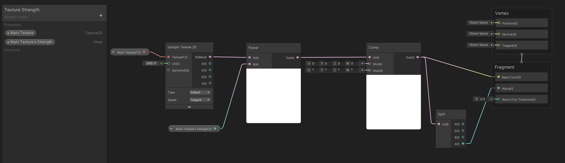
All of the magic really happens with the ‘Power’ node. Here we take our ‘Sample Texture 2D’ node with our texture plugged in and run it through the ‘Power’ node where we also have our custom float value (which we will control in Editor) attached. We then run the result through the ‘Clamp’ node to avoid artifacts and plug in the result in the Base Color of the Fragment section. We also split the result to get the Alpha of the texture (so that we could see the texture’s transparent parts) and attach it to the Alpha channel in the Fragment section.
In the ground crack example above, I also have another black outline texture beneath the main crack texture where we control its strength, basically, I just added them together and also assigned different colors.
Dissolving objects with a noise texture
If you are tired of making objects appear/disappear by scaling them up/down or just simply fading in/fading out then this ShaderGraph is for you 😉 Here we have endless possibilities to make the objects appear/disappear in a fun and creative way – you just need various noise textures that will provide different results. You will find this technique in nearly all of the more pretty/advanced effects combined with opacity control as it brings such satisfying dissipation of the objects.
This is the noise texture is used in the example above to dissolve the sphere. The stripes appear horizontal because the sphere was rotated.

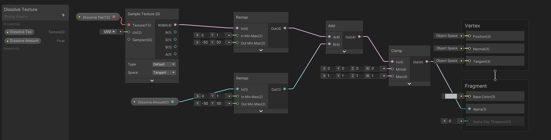
In this ShaderGraph you will plug in your noise texture into a ‘Remap’ node where the In Min Max channel x=0 and y=1, and the Out Min Max channel x=-50 and y=50 (these last values are not set in stone, you can tweak them to your needs). With this ‘Remap’ node we just basically assign texture’s values (that are ranging from 0 to 1 (black=0 and white=1)) and just remap them to the new current values, 0 will become -50, and 1 will become 50. We add up the result with another ‘Remap’ node where the values are the same, but this time we assign a float value which we will control in the Editor. Once we start changing the float’s values it will appear that the texture is dissolving or growing in the texture’s patterns. We then run the result through the ‘Clamp’ node and output it to the Alpha channel in the Fragment section.
In the example above I also added colors and texture panning to the spheres that are very similar in size. You can also ditch the noise textures and use the procedural noise nodes, however, keep in mind that they are quite expensive if you are planning to use them in production.
Depth Fade
Are you sick of hard edges when two objects intersect? I know I am, and that’s why I use this ShaderGraph frequently. Shortly, this shader is very similar to the default ‘Soft Particle’ shaders and the ‘Soft Particle’ property in VFX Graph – it softens out the hard edges when two objects or particles intersect. This ShaderGraph is also useful for such effects as smoke, mist, fire – anything that is quite light in texture and is supposed to be transparent in nature.

In this ShaderGraph, we take the ‘Screen Position’ node and set it to ‘Raw’. The ‘Screen Position’ node basically allows us to access a mesh vertex or fragment’s Screen Position. By default, this value divides the screen position by the clip space position W component, and as useful as it may be for projecting things, we only need the Raw value to make some calculations ourselves! We ‘Split’ the ‘Screen Position’ node through the Alpha channel so that we could get only the Z information. We subtract the Z information from the ‘Screen Depth’ node which is set to ‘Eye’. The ‘Screen Depth’ node allows us to access the Camera’s depth buffer and as we set it to ‘Eye’, it will now return the depth converted into eye space units. We take the given result and divide it from a float value that goes through the ‘Maximum’ node where the X value is set to 0.0001. This is done so that we would not try to divide by zero, sort of as a fail-safe 🙂 The closer our float value is to 0.0001, the harder the edge will be, the bigger the value – the softer. We then put the result through the ‘Smoothstep’ node which just smoothes out the overall fade (if you are interested in how the smooth-step function works you can watch a video about it here). Finally, the whole shader node group goes into the Alpha channel in the output Fragment section as we will be controlling the Alpha of the object.
Opacity
It may be simple, but I use it every day – very useful for fading in and fading out objects.

In this ShaderGraph we just take the float value and run it through the Lerp node where the B channel is set to 1 and the T channel is set to 0. We then output it to the Alpha channel in the Fragment section.
If you also have a custom texture in the shader and want to see the transparency and also control overall opacity you should multiply the texture’s alpha channel with the ‘Lerp’ node’s result.
Vertex displacement according to texture’s values
This is a super useful shader to give your effects some movement, or if you are lazy – extrude some parts of the mesh without modeling (I used this technique in one of my projects to create a lava lump). You can use this technique to add some movement into a fog, make a flickering fire, create an ocean with moving waves… The possibilities are endless.

This is the noise texture is used in the example above to displace the vertices.
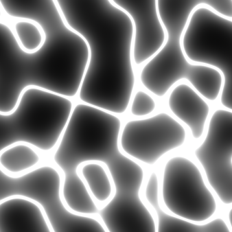
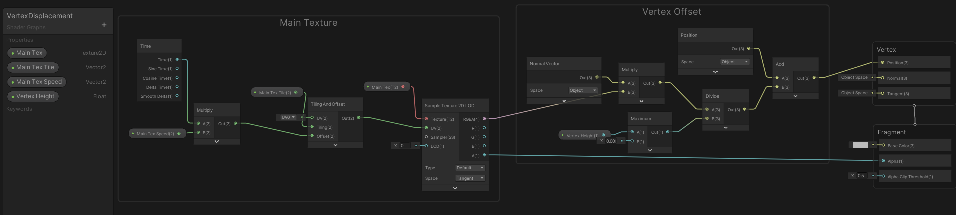
This ShaderGraph is split into two parts – Main Texture and Vertex Offset. In the Main Texture group, we input our Texture 2D property into the ‘Sample Texture 2D LOD’ node. We are using the LOD node and not the default one because only the LOD version works in the Vertex shader stage. We then input the ‘Tiling and Offset’ node with custom floats and the ‘Time’ node so we could make the texture scroll and tile. In the Vertex Offset group, we multiply our texture with the ‘Normal Vector’ node-set to Object. Basically, we are multiplying RGBA values with the normal vectors of the object and then adding new positions for them, controlling the height. The white parts of the textures have a value of 1,1,1 while the blackest parts have 0,0,0, and the grays range between the white values and black values, so that means between 0,0,0 1,1,1 and 1,1,1. When we multiply these values with the ‘Normal Vector’ node, the white parts will have a bigger value than black, thus will appear higher, and the black will be lower, thus will appear lower. The ‘Divide’ node is there so that we could have smaller values and could control the height of the fog. We run our float value through the ‘Maximum’ node so that if we ever choose zero value it will be converted to 0.0001 so that we wouldn’t divide it by zero. Finally, we get the object’s position with the ‘Position’ node set to Object and add it with our new vertex positions. The results are then plugged into the Position channel in the Vertex shader section.
In the example above I added this shader to a sphere, turned on some color, and just made the texture scroll. Looks like a fancy alien egg 👽
Don’t stop here… Apply your knowledge!
I really encourage you to take some time and experiment with the shaders. Try to mix these shaders into one master shader, add some colors, and use various noise textures and procedural noise nodes – have some fun! The more you experiment, the more you will understand how the shaders work.
If you are looking for something more structured, I created a tutorial called ‘How to create a low-lying fog with Unity’s ShaderGraph‘. There you will find some of the shaders that were mentioned here but you will also apply them in a practical way.
I hope you found these shaders useful, happy creating!